SIS-TECH

We're proven in use

  • enEnglish
  • Registration
  • Log In

Search

  • Solutions
  • Applications
  • Field Services
  • About Us
  • Careers
  • Contact Us
  • SIS-TECH University
  • SIS-TECH Advantages
  • DIAMOND-SIS®
  • ICE-Manager™
  • SIL Solver®
  • News & Press
  • Publications

Achieving risk reduction requires maintenance and timely repair

June 2018

Being able to quickly and safely maintain your instrumented safeguards is essential to maximizing process uptime. Maintenance facilities and procedures should always be factored into front-end loading estimates for instrumented safeguards. However, it is likely that many sites have encountered projects, where provisions for maintenance, test and repair were treated as an afterthought.

The failure rates assumed during the verification of the risk reduction are based on the timely performance of the routine planned preventive maintenance (PPM). The reliability of an instrumented safeguard also depends on the scope and timing of periodic inspections and the timeliness of any needed repair when a fault is detected. Procedures and maintenance facilities can be needed shortly after start-up, as early failures are found and planned maintenance work begins.

An effective plan for instrumented safeguard maintenance can impact:

  • equipment and piping – taps, bleeds, valves, maintenance bypass lines, spare parts strategies
  • operating strategy – whether to commit to always coming down to safe state for test and repair or alternatively to design for on-line maintenance and repair activities
  • organizational plans – need sufficient numbers of competent personnel to execute the activities, capture the relevant performance data, and investigate abnormal behavior

The following case study highlights an incident where there was plenty of evidence that the existing equipment was not performing as needed. A change in the instrument specification was also not carried forward into the maintenance procedures, so the criticality of a maintenance task was unrecognized by the technicians executing the test. Changes in equipment technology often impact maintenance procedures, but if the management of change process does not drive personnel to examine the maintenance procedures, the disconnect between the field and the procedure can have significant safety impact, as illustrated by the Hemel Hempstead incident.

Case Study Example:

Fuel storage; Hemel Hempstead, England; December 11, 2005

Impact: Explosion and fire; 43 injuries; 2,000 evacuated, commercial and residential damage

Summary

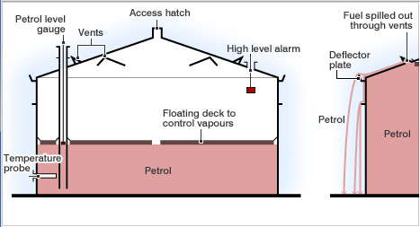
Gasoline was being delivered to the tank on the day before the incident. Early the next morning, the Automatic Tank Gauging (ATG) system displays an unchanging level, although the tank continued to fill. By practice, the operator controlled level by terminating transfer upon receipt of the user alarm. However, the ‘user’, ‘high’, and ‘high high’ level alarms used the same transmitter, so the failure of the shared transmitter rendered these alarms inoperative. Since the alarm never activated, the operator did not take action to terminate transfer.

An independent high-level switch, set above the ATG high-high level, was designed to close inlet valves and activate an audible alarm, but it also failed. The high level switch had been disabled when the maintenance organization, due to lack of understanding of the relatively new technology and to insufficiently detailed procedures, did not reinstall a lock on the switch test arm. Without the lock, the level switch was not activated when the float was lifted. By late afternoon, the tank overfilled and contents spilled out of tank roof vents. A vapor cloud was formed and noticed by tanker drivers and by people outside the facility. The fire alarm was activated and firewater pumps were started. An explosion occurred a short time later, likely ignited by the startup of the firewater pumps.

Instrumentation and Controls Gaps

  • Analog level had 14 dangerous failures (stuck) in preceding 3.5 months
  • Safety implications of frequent analog level dangerous failures not noted or logged
  • 3 level alarms did not activate due to same analog level failure
  • High level switch interlock failed due to undermanaged instrument technology change performed by maintenance group ~18 months earlier

Key Automation Learning Points

It is critical to train maintenance staff to properly test equipment and to verify that the equipment has been properly returned to service. The fault response and repair procedures should include a check for unacceptably high failure rates. Written instructions should be provided on how to escalate these situations to maintenance and facility leadership for investigation and correction.

In the above case, a control instrument with abnormally frequent failures (a maintenance “bad actor”) went unreported. The only independent safeguard failed due to an instrument technology change that was not effectively incorporated into the maintenance program.

Sustainability Actions

  • Work checks for abnormal failures and to whom among leadership to escalate this information to should be incorporated into the detailed written maintenance procedures
  • A change to make, model, or electronic version number consider the maintenance strategy and ensure that PPM and test procedures are updated and maintenance personnel retrained if needed.

References:

  1. 2007. Buncefield Standards Task Group (BSTG) Final Report. UK: Health and Safety Executive.
  2. 2017. Guidelines for Safe Automation in Chemical Processes-2ed. New York: AICHE.
  3. Summers, Angela E., E. Roche, H Jin, M Carter. 2015. “Incidents That Define Safe Automation.” Presented at 61st International Instrumentation Symposium, Huntsville, Alabama, May.

SIS Myth Busting

June 2018

Myth 1: Application programming for modern safety PLCs is so easy that anyone can do it.

With drag-and-drop interfaces, function blocks and some training, you would think that almost anyone could program a PLC. But translating critical safety logic into a PLC application program requires close cooperation among programmers, process control engineers, and operations and maintenance personnel to ensure that the application program supports plant operation, as well as safe operation.

A program specification should be developed and approved prior to PLC programming. Some PLCs have tools that translate the program as written into an engineering document. This is great for debugging the program, but it is not the same as programming and validating the system operation per an approved specification. Through a debugging exercise, you can obtain a program that under certain test conditions will do what you intend, but this program can have significant hidden problems that will not be seen until conditions change. A program with latent bugs can negatively impact system reliability and risk reduction. Disorganized and complex programming can yield an application program that’s difficult to understand, properly test and safely modify.

SIS-TECH has experience with all major brands of PLCs.  Whether Emerson, Honeywell, Siemens, Allen-Bradley, Yokogawa, HIMA, Triconex, or any other PLC, SIS-TECH can execute turn-key projects in critical control, alarm, interlock and SIS applications. For more information on SIS-TECH’s independent engineering services, contact Eric Randecker, erandecker@sis-tech.com or 832-434-7307.

Grandfathering of Existing SIS

June 2018

Step 1. Confirm Hazard and Risk Analysis (H&RA) assumptions

The Hazard and Risk Analysis establishes the preliminary risk management strategy. The supporting documentation contains assumptions related to automation reliability and the capability of on-site staff to sustain the system. Examples of common assumptions include:

  • Well trained operations who reliably use written procedures
  • Facility only operates under the conditions evaluated in the H&RA
  • Facility does not intentionally violate the safe operating limits (throughput, process conditions, etc.)
  • Adequate staffing levels of operations and maintenance technicians to address faults and discrepancies in a timely manner
  • An effective alarm management program is in place
  • Instruments are fit-for-use for the process applications
  • Low demand rate on the instrumented safeguards
  • Independence between causes and safeguards exists

Functional safety practices dictate that the site verify the  H&RA assumptions. IEC-61511:2016 requires the determination that the design, operation, maintenance, and testing are sustaining the safety integrity as required by the site risk management strategy. ANSI/ISA-18.2 requires that alarm events be monitored to ensure effectiveness of the alarm system. Gaps between the assumptions and reliability can have both direct and indirect impact on actual site risk.

Case Study Example:

Natural gas processing; Longford, Australia; September 25, 1998.

Impact: Explosion and fire; 2 fatalities; 8 injuries; Plant 1 destroyed, Plants 2 and 3 shutdown, 5% loss of supply, 250,000 workers sent home.

Control instrumentation for absorber bottoms condensate

 Summary

The LPG Plant 1 separated methane from LPG in a pair of absorber towers using lean oil. During the night before the accident, the level increased in the knockout section of Absorber B. Since the disposal route to Plant 2 was not available, an alternate route to a Condensate Flash Tank was used. The normal procedure of increasing absorber bottom temperature was not done. As a result, the flash tank protected itself from excessively cold temperatures by decreasing incoming flow, which in turn caused absorber condensate level to continue to increase. Eventually, condensate mixed with rich stripping oil. This mixture flashed across the level control valve and lowered the temperature in the Rich Oil Flash Tank. Temperatures throughout the plant were lowered as rich oil flowed through the process. A low temperature trip of the lean oil pumps resulted, and the trip was not communicated to the plant supervisor for over an hour. A hand switch was actuated to decrease flow through exchanger GP905 in an attempt to restart the pumps. The heat exchanger ruptured due to cold temperature embrittlement, releasing a vapor cloud of gas and oil. The cloud traveled 170 meters to fired heaters before ignition occurred.

Instrumentation and Controls Gaps

  • 100s-1000s of alarms happened per day, many regarded as nuisance
  • Critical alarms were not prioritized
  • Operators desensitized, alarm system ineffective
  • Operators and supervisors did not understand the consequences of their manual actions and experienced engineers had been moved off-site

Key automation learning points

Alarm management reduces the number of alarms to only those requiring operator action. The risk reduction that normally results from a robustly managed safety alarm program is fully dependent on timely and correct operator response to the alarms. Having chronically high process alarm rates in a facility or a significant number of alarms which do not require action will promote the development of ineffective alarm response habits. [ANSI/ISA 18.2]

As in most large events, there were many contributing factors. Among them were two significant deviations from common H&RA automation assumptions:

  • The facility was operating in an alternate mode in which operations and the front-line supervisors, in the absence of experienced engineers, did not correctly understand how the process conditions would respond to the manual actions they took.
  • The alarm management system was ineffective, with chronically high levels of unprioritized alarms, fostering desensitization to and basic distrust of alarms by the operators.

With these deviations from standard H&RA assumptions, any Operator Response to Alarm protection layer would be very unlikely to succeed.

Sustainability action

Audit to confirm that the assumptions made during hazard and risk analysis are actually reflected in plant operation and that these assumptions remain valid over time.

References:

  1. Hopkins A. 2000. Lessons from Longford: The ESSO Gas Plant Explosion. CCH Australia Limited.
  2. 2017. Guidelines for Safe Automation in Chemical Processes-2ed. New York: AICHE.
  3. Summers, Angela E., E. Roche, H Jin, M Carter. 2015. “Incidents That Define Safe Automation.” Presented at 61st International Instrumentation Symposium, Huntsville, Alabama, May.

Incidents That Define Safe Automation

October 2017

The process safety management regulation was issued in 1992 to address the prevention or minimization of the consequences of catastrophic releases of toxic, reactive, flammable, or explosive chemicals. In the decade leading up to its promulgation, the process industry suffered significant loss events that caused worldwide attention to become focused on reducing the risk of process safety events. To emphasize the importance of safe automation, case studies of previous incidents are presented, including a brief description of the incident and the major lessons to be learned. There are typically many contributors to these incidents and some incidents have become synonymous with certain safety issues, e.g., Texas City 2005 related to siting of temporary and permanent structures. This paper does not make any attempt to replicate these previous lessons learned, but instead focuses on the contribution of inadequate design, installation, testing, maintenance, and operation of the process control and safety systems.

Are Your Safeguards Fast Enough To Be Effective?

July 2017

Presented at AIChE 2017 Spring Meeting, and Global Congress on Process Safety 2017.
A core attribute of all safeguards is that they must be functional against the loss event in question and one of the essential elements of functionality is speed. How to determine the response time available for a given safeguard to complete its action is a common project question. Several instrumentation and controls design pitfalls should be avoided when specifying the response time. A variety of engineering practices, from basic to advanced, may be used to justify the selected value.

Introduction to Functional Safety Assessment of SCAI

July 2017

A functional safety assessment (FSA) is a tool used to identify and correct defects before a simple human error allows an incident to propagate in spite of the capital spent on the installed SCAI equipment.
Presented at ISA 2016, MKPOSC International Symposium 2016, Global Congress on Process Safety, 2017. Accepted for publication in Process Safety Progress.

Approved Equipment Selection Creates Reliability

April 2017

Dr. Angela Summers

Automation equipment in control applications is selected primarily based on operational needs, such as functionality, reliability, repeatability, accuracy, communication options and ease of maintenance. Demonstrated in-service performance earns the equipment and its manufacturer a coveted place on the approved equipment list. Equipment in safety applications must also support risk reduction requirements. For safety instrumented systems (SIS), approving the initial selection and continued use of equipment based on in-service performance is referred to as “proven in use” in International Electrotechnical Commission (IEC) 61508 and “prior use” in IEC 61511. Ultimately, the intent of both standards is to collect data that proves the installed equipment is capable of providing satisfactory performance.

Manufacturers often make safety integrity level (SIL) claims on their products. However, SIL is a loop concept and not a device property. An SIL 1 sensor connected to an SIL 1 logic solver with an output to an SIL 1 final element may not achieve an SIL 1 loop. The strength of a chain depends on the total strength of its links. Like a weak link in a chain, the weakest subsystem will limit the integrity of the loop. In many cases, it is necessary to design some, if not all, of the subsystems (the links) to achieve a higher SIL claim so the loop (the chain) design meets the required SIL. Of course, the actual loop performance will also depend upon operations and maintenance management systems.

The most troublesome result of the IEC 61508 certification process is how unconservative the manufacturer claims appear to be. The failure rate data published by various industry data collection programs have revealed in-service dangerous failure rates are significantly higher than what is claimed in the majority of third-party approval reports. For field devices, the reported values are generally 3-10 times lower than what is seen in actual installations. For programmable logic controllers, the manufacturer’s claims can be unconservatively lower than in-service performance by a factor of 10 or more. This means a lot of certified equipment is being sold based on an SIL claim at least one level higher than achievable in the installation.

IEC 61511 only requires the use of safety-certified controllers in SIL 3 applications. For all other technologies and applications, IEC 61511 clause 11.5.2.1 states, “Devices selected for use as part of an SIS with a specified SIL shall be in accordance with IEC 61508-2:2010 and IEC 61508-3:2010, and/or 11.5.3 to 11.5.6, as appropriate.” This clause lists two forms of evidence that can be used to select devices for SIS applications:

• Evaluation for compliance with IEC 61508 Part 2 (hardware) and Part 3 (software). This typically involves a third party approval of a specific configuration of a product.

• Prior use or historical data. These data are typically derived from the device’s performance in similar operating environments.

When weighing these two forms of evidence, the more relevant the information is to the in-service environment, the higher the certainty will be that the actual performance will be consistent with the assumed reliability parameters.

Ultimately, the intent of both standards reinforces that there should be sufficient evidence for site personnel to have confidence that the equipment as installed is suitable for the operating environment, meets the risk reduction requirements and is fit for purpose. Practically, every site has different organizational strengths and capabilities. One site may be perfectly capable of supporting a particular technology, while another site may not be. The effect of the process fluid or external environment on a device can be more severe at one site than at another. These factors are typically excluded from an IEC 61508 analysis. Prior use evidence ensures the selected equipment can be dependably specified and implemented in a way that minimizes the potential for random failures and human errors within that site.


SIS-TECH Solutions Introduces it’s Tank Monitoring and Overfill Protection System

April 2017

Houston, TX – SIS-TECH Solutions introduces its tank monitoring and overfill protection system using the latest version of the Diamond-SIS. The fully integrated system is easy to apply, making it an economical solution from both a capital and installation cost perspective. The Diamond-SIS has a 15 year history of reliable and trustworthy protection of critical assets. Its durability allows it to be locally installed, while its fast delivery time make it the perfect choice for tank retrofits and new construction.


SIS-TECH Commissions Largest Diamond-SIS® To Date

April 2017

Houston, TX – Pete Fuller, applications advisor at SIS-TECH, has commissioned the largest Diamond-SIS® (safety instrumented system) to date. The burner management system ensures safe start-up of a six burner heater with purge permissives and light-off. Onboard LEDs display real-time burner status, giving outside personnel a clear indication of which burners are lit and which valves are open.

The ease of use and lack of programming make the Diamond-SIS a cost-effective choice for heater protection. The site has chosen the Diamond-SIS as its preferred small-input/ output safety instrumented system. Additional projects have been initiated for an eight-burner and a 12-burner heater.

For more information, call (713) 909-2100.


Bob Brown Hired as Director of Strategic Corporate Accounts

April 2017

Houston, TX – SIS-TECH Solutions has hired Bob Brown as director of strategic accounts. Bob has over 35 years in the Petrochemical industry focused on the challenges of process safety. He also holds membership in committees that include ASME, ISA, Texas A&M’s Mary Kay O’Connor Process Safety Center, and RPSEA. In his new role, Bob will continue his focus on process safety offering clients options to create an inherently safer work place.


  • 1
  • 2
  • 3
  • …
  • 16
  • Next Page »

Call one of our Experts
713-909-2100

Get a quote today.

get quote

Questions? Please Contact Us.


For full access:
Login
Registration

Receive updates on SIS-TECH


By submitting this form, you are consenting to receive marketing emails from: . You can revoke your consent to receive emails at any time by using the SafeUnsubscribe® link, found at the bottom of every email. Emails are serviced by Constant Contact

SIS-TECH Solutions LP
We’re Proven in Use®

12621 Featherwood, Ste 120, Houston, TX 77034
| P: 713-909-2100
| F: 281-922-4362


| © 2011-2016 SIS-TECH
Privacy Policy
Go To Top