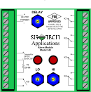
The Diamond SIS® is designed as a low-cost, stand-alone, non-PE logic solver for process industry applications.
- The Diamond SIS® is SIL 3 Compliant to IEC 61508. Rated for -30C to +75C, it can be installed even under the harshest conditions near the equipment under control, reducing implementation costs.
- The Diamond SIS® receives an analog or digital process signal. Two field-adjustable set points allow shutdown to be executed for high and low process signals. Serial or hardwired communications are used to remotely display process variables and system alarms.
- With its 5 Amp output rating, the Diamond SIS® can de-energize multiple final elements, including motor control circuits and/or solenoid operated valves.
- System power for the Diamond SIS® is 24VDC, 110VAC, and 240VAC and is provided with redundant power supplies and/or UPS.
- The Diamond-SIS® can repeat the signal to any other control system for display and alarming.

KEY FEATURES
- IEC 61508 SIL 3 Compliant
- High reliability
- Proven technology
- Rugged design
- Field mountable
- On-line testable & repairable
- Remote process variable & system status monitoring
- Signal communication to control systems
- No programming
- Class 1, Div 2
- Low installed cost alternative to a Safety PLC
- ENGINEERING/DOCUMENTATION OPTIONS
Safety requirements specification, SIL Verification and Proof Test Procedures.
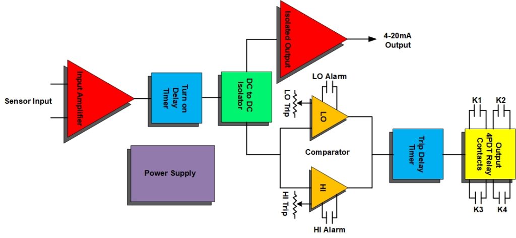
Each Diamond SIS® consists of the following elements:
- Power Supply
- Input Amplifier (I/U converter, differential or single ended input)
- Turn-on delay timer
- DC to DC Isolator
- Isolated Output amplifier
- Comparator High/Low
- Trip delay timer
- Output – Dry Relay Contacts

POWER SUPPLY
The power supply receives an external +24Vdc to generate the internal Vcc voltages incorporated by the Diamond-SIS. Polarization and over-current protection circuits keep the Diamond-SIS fault free.
INPUT AMPLIFIER
The high precision, low compliance voltage current loop receiver converts a differential or single ended sensor current input (4-20 mA) into an equivalent voltage level. It also provides an external voltage reference for the comparators so that any shift in reference voltage will be ratiometric and will not influence the trip thresholds.
TURN ON DELAY TIMER
The turn on delay timer prevents relay flutter when the supply voltage to the channel electronic is applied. It holds the input in the “OFF” state until the internal Vcc supplies have stabilized and the Diamond-SIS has detected the process condition. The turn on delay timer does not influence the trip delay time.
DC TO DC ISOLATOR
The analog input, analog output, alarm contact outputs and the 24Vdc power are mutually isolated. This accomplished by first converting the analog input into a digital signal. The digital signal is then optically isolated twice. Isolated power for the analog input and output circuitry and their associated loop supplies are handled by a single push-pull chopper, driving four transformers.
ISOLATED OUTPUT
The digitized analog signal is converted back to a 4-20mA signal precisely repeating the process input.
LO COMPARATOR
The low comparator compares the I/U converted sensor signal with a preset trip threshold. The threshold voltage is adjusted via a high precision 10-turn potentiometer. If the sensor signal falls under the threshold, the comparator changes output and the trip delay circuit is triggered. The low comparator output will also trigger and hold on a detected open loop.
HI COMPARATOR
The high comparator compares the I/U converted sensor signal with a preset trip threshold. The threshold voltage is adjusted via a high precision 10-turn potentiometer. If the sensor signal raises above the threshold, the comparator changes output and the trip delay circuit is triggered. The high comparator output will also trigger and hold on a detected shorted loop.
TRIP DELAY TIMER
The trip delay timer circuit delays the actuation of the output relay by an adjustable time. (.2 – 20 seconds). The trip delay timer is not asserted when the process returns between the high and low threshold of the comparator. The delay time is adjusted via a high precision 19-turn potentiometer.
OUTPUT RELAY
If the sensor signal exceeds the low or high threshold longer than the trip delay time, the output relay is activated. If the sensor signal returns into the normal range before the delay time has expired, the outputs are not activated.
SPECIFICATIONS
Supply Power: User specified, 24VDC/110VAC/240VAC
Input: 4-20 mA DC or discreet (dry contact)
Output: 5 Amp resistive dry contact
Accuracy: 1% of span
Temperature: -40 to +80oC Storage / -30 to +75oC Operating
Environment: All internal components rated Class I Div II Groups A/B/C/D
Enclosure: NEMA 4X – choice of materials
This is a direct replacement for the Model 340.


